

close
Choose Your Site
Global
Social Media


Lithium battery charging often carries persistent anxiety stemming from the volatile thermal runaway risks associated with early lithium-ion chemistries like lithium cobalt oxide. Modern Lithium Iron Phosphate (LiFePO4) batteries offer inherent structural stability, fundamentally changing how we approach power storage. However, applying legacy lead-acid charging profiles—such as constant trickle or float charging—to modern LiFePO4 systems risks premature capacity fade or complete system failure. Trusting non-optimized charging hardware compromises the electrochemical integrity of the cells.
Safely leaving a battery connected depends entirely on the system's hardware ecosystem. The algorithmic synergy between a dedicated LiFePO4 Charger, correct voltage termination parameters, and the internal Battery Management System (BMS) dictates whether continuous connection is a viable operational strategy or a critical failure point.

Hardware Dependency: Leaving a LiFePO4 battery on a charger is safe only if utilizing a smart, dedicated LiFePO4 charger that features an automatic charge termination protocol (0A cut-off) or a strictly regulated, non-prolonged float stage.
The BMS is a Failsafe, Not a Regulator: Relying solely on the battery’s internal BMS to halt charge cycles is a high-risk operational strategy; the charger itself must govern the voltage profile.
Continuous Float Risks: Holding a LiFePO4 battery at 100% State of Charge (SoC) indefinitely via a continuous high-voltage float (above 3.4V per cell / 13.6V for a 12V pack) accelerates calendar aging and parasitic side reactions.
Multi-Stage Incompatibility: Legacy lead-acid trickle chargers utilize desulfation pulses and high-voltage equalization phases (exceeding 15.5V) that can permanently damage LiFePO4 cells and trigger immediate BMS lockouts.
Table of Contents
Mechanically, it is safe to leave a LiFePO4 battery connected to a certified charging unit. The chemistry boasts high thermal stability and resistance to oxygen release, meaning it will not spontaneously ignite under normal conditions. You will not burn down your shop or RV simply by leaving the unit plugged in. However, maintaining a continuous connection is not optimal for maximizing total cycle life.
Immediate safety hazards differ drastically from long-term electrochemical degradation. Sustaining a high state-of-charge accelerates electrolyte oxidation and promotes lithium plating. When you hold a lithium cell at 100% capacity, the internal voltage pressure forces lithium ions into the graphite anode constantly. Over months of continuous connection, this mechanical stress degrades the lattice structure, permanently reducing the amp-hour capacity of the pack.
Continuous connection requires strict operational conditions to prevent this degradation. Active charge termination must be present, ensuring no continuous trickle current flows once the battery reaches full capacity. A certified, fully operational BMS must monitor the pack, and ambient temperatures must remain within safe charging windows. If you operate in cold climates, the ambient temperature must stay above freezing unless you utilize an internal self-heating system.
Operational Metric | Short-Term Safety Impact | Long-Term Longevity Impact |
|---|---|---|
Continuous 14.6V Connection | Safe (BMS will eventually intervene) | Severe capacity fade over 12-24 months |
Continuous 13.5V Float | Safe (Below degradation threshold) | Moderate calendar aging, acceptable for standby |
Disconnected at 50% SoC | Maximum Safety | Maximum cycle life preservation |
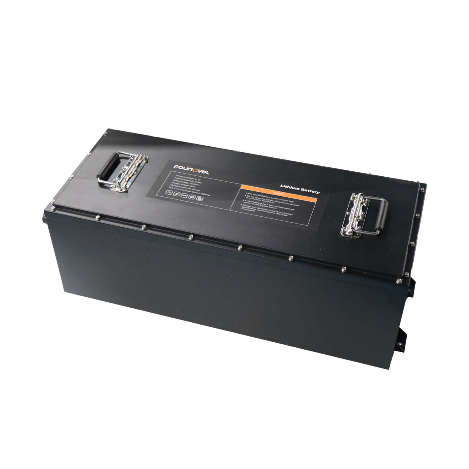
A true LiFePO4 Charger utilizes a strict Constant Current / Constant Voltage (CC/CV) algorithm. This two-stage process respects the electrochemical limits of the cells, ensuring energy transfers efficiently without generating excessive heat.
Bulk Stage (Constant Current): The unit pushes maximum safe current into the battery. The voltage climbs steadily as the state of charge increases. The charger maintains this maximum amperage until the battery voltage reaches the target absorption limit.
Absorption Stage (Constant Voltage): Once the target voltage is reached—typically between 14.2V and 14.6V for a 12V battery—the charger holds the voltage steady. As the internal resistance of the battery rises near 100% SoC, the current naturally tapers down toward zero.
Termination Stage: When the current drops to a specific termination threshold, usually 0.02C to 0.05C, the charger terminates the cycle completely.
The critical cut-off point separates lithium-specific hardware from legacy chargers. It enters a standby mode rather than transitioning to a continuous trickle charge. Lead-acid batteries suffer a high self-discharge rate of 5-15% per month, necessitating constant maintenance charging to prevent sulfation. LiFePO4 cells exhibit an ultra-low self-discharge rate of 2-3% per month, rendering continuous maintenance charges obsolete.
If a charger must remain connected to support DC loads, a safe "storage float" voltage must not exceed 13.5V to 13.6V for a 12V system. This voltage sits just below the natural resting voltage of a fully charged cell, providing power to external loads without forcing additional current into the battery chemistry.
Understanding voltage parameters across different system sizes prevents accidental overcharging and ensures hardware compatibility. When wiring larger banks in series, the voltage multipliers require precise charger calibration.
System Size | Cell Count | Target Bulk/Absorption | Safe Max Float | BMS HVD Trigger |
|---|---|---|---|---|
12V LiFePO4 | 4-Cell | 14.4V - 14.6V | 13.5V - 13.6V | ~14.8V |
24V LiFePO4 | 8-Cell | 28.8V - 29.2V | 27.0V - 27.2V | ~29.6V |
48V LiFePO4 | 16-Cell | 57.6V - 58.4V | 54.0V - 54.4V | ~59.2V |
Applying a 12V profile to a 24V system will simply fail to charge the bank. However, applying a 48V profile to a 24V system will immediately trigger the BMS High-Voltage Disconnect. If the BMS fails under that load, the cells will swell and vent. Always verify the nominal voltage of your charging hardware matches your battery bank configuration before making the physical connection.
Dedicated AC-to-DC lithium chargers represent the gold standard for system safety. They prevent over-voltage through hard-calibrated voltage ceilings and often include zero-volt "wake-up" features. When a BMS trips due to low voltage, it severs the connection, making the battery appear dead to standard chargers. A dedicated lithium unit sends a small pulse to wake the BMS, close the circuit, and begin the bulk charge phase.
Multi-chemistry smart chargers offer selectable lithium profiles, but introduce user-error risks. Selecting an AGM or Gel profile by mistake applies destructive equalization algorithms. Operators must verify that the lithium profile actively disables desulfation and temperature compensation. Lead-acid chargers increase voltage as temperatures drop. Applying this temperature compensation to lithium in cold weather will push the voltage dangerously high, destroying the cells.
Solar charge controllers require precise custom parameter configuration for arrays left permanently connected. You must program the Maximum Power Point Tracking (MPPT) controller to respect lithium limits.
Set the absorption voltage to 14.4V.
Set the absorption time to a maximum of 30 minutes per 100Ah of capacity.
Set the float voltage to 13.5V, or disable the float phase entirely.
Disable all equalization stages.
Utilizing legacy lead-acid chargers presents a high-risk approach. Lead-acid algorithms misinterpret a full LiFePO4 battery's voltage behavior. Because lithium maintains a flat voltage curve until it is nearly full, a lead-acid charger assumes the battery is deeply discharged and pushes high voltages endlessly. This triggers safe mode trips due to incompatible pulsing profiles.
The BMS provides primary safety functions, including per-cell voltage monitoring, thermal tracking, and over-current protection. If a non-optimized charger pushes voltage beyond safe limits, the High-Voltage Disconnect (HVD) dynamics activate. The BMS acts as a circuit breaker, severing the physical connection to protect the cells from over-voltage stress.
Relying on the BMS to terminate daily charge cycles stresses internal MOSFETs. A BMS operates as an emergency protection device, not a primary charge controller. MOSFETs are solid-state switches that generate heat when opening and closing under load. Forcing the BMS to repeatedly trip its HVD leads to component fatigue. Eventually, the MOSFETs will fail in the closed position, removing all protection from the battery and allowing the charger to destroy the cells.
A minor, controlled hold at the top of the charge cycle near 14.4V allows the BMS shunt resistors to bleed off energy from high cells, facilitating passive balancing. The BMS identifies cells that reach 3.65V first and applies a small resistive load, usually 50mA to 100mA, to slow their charge rate while the lower cells catch up. This requires periodic top-charging to keep the pack balanced, but strictly prohibits continuous, long-term connection. Once the pack is balanced, the charger must shut off.

Storing batteries fully charged initiates a degradation loop. Holding LiFePO4 at a 100% state-of-charge increases internal resistance and accelerates capacity fade due to structural stress on the cathode. The optimal storage strategy involves disconnecting chargers entirely and maintaining batteries at 50% to 70% SoC in temperature-controlled environments. A resting voltage of approximately 13.2V indicates an ideal storage state for a 12V pack.
Managing parasitic loads in RVs, marine vessels, or off-grid cabins complicates storage. Persistent draws from CO2 detectors, clocks, radio memory, or inverter standby modes deplete batteries over time. If you leave a battery connected to a vehicle system over the winter, these milliamp draws will completely flatten the pack by spring, potentially triggering the Low-Voltage Disconnect (LVD).
Operators must evaluate the trade-off of keeping a charger connected to handle these loads versus installing a manual battery disconnect switch. A heavy-duty marine disconnect switch physically isolates the battery from all loads, eliminating parasitic draw entirely. Premium chargers often feature a "Power Supply Mode," which bypasses the battery charging algorithm and powers DC loads directly at a flat 13.5V, offering a viable compromise if you need to keep onboard systems active during storage.
Grid power fluctuations introduce hidden risks for continuous connection. When power drops and returns, non-optimized smart chargers may restart their bulk charging phase from scratch. Because a full lithium battery rests at a relatively low 13.3V to 13.4V, a basic charger assumes it needs a full cycle. This pushes a full battery back through a high-voltage absorption cycle, risking over-charging. High-quality hardware mitigates this through intelligent voltage sensing, recognizing the battery is full and immediately returning to standby mode.
Low-temperature charging presents severe dangers. Charging below freezing causes lithium plating. The lithium ions cannot intercalate into the graphite anode fast enough at low temperatures. Instead of absorbing into the structure, they accumulate on the surface as metallic lithium. This permanently reduces capacity and creates internal short-circuit risks. A robust system requires Low-Temperature Cut-Off (LTCO) protection to halt current flow during winter storage. You must verify that either your BMS or your charger includes a dedicated thermal probe to enforce this cutoff.
Charger calibration drift occurs over time. Internal components age, and the voltage output can shift. Operators should use a high-quality digital multimeter to periodically verify that an aging charger's actual output matches its programmed target voltages. Measure the voltage directly at the battery terminals during the absorption phase. If the charger is programmed for 14.4V but the multimeter reads 14.8V, the unit requires replacement before it damages the battery bank.
Leaving a LiFePO4 battery on the charger can be safe when using a dedicated LiFePO4 charger with the correct charging profile and a reliable Battery Management System (BMS). Choosing compatible charging equipment and following proper charging practices are essential for maximizing battery lifespan, maintaining performance, and protecting your investment.
About Polinovel
Polinovel is a professional manufacturer of LiFePO4 batteries for solar energy storage, RVs, marine systems, golf carts, forklifts, and industrial applications. Combining premium Grade A cells, intelligent BMS technology, advanced manufacturing processes, and strict quality control, Polinovel provides safe, reliable, and long-lasting lithium battery solutions trusted by customers around the world.
Always use a dedicated LiFePO4 charger with the correct CC/CV charging profile.
Verify charger compatibility, charging voltage, and Battery Management System (BMS) protection before continuous charging.
Avoid long-term high-voltage float charging unless specifically recommended by the battery manufacturer.
Choose certified lithium batteries from manufacturers with proven engineering expertise and dependable technical support.
Before leaving your LiFePO4 battery connected to a charger for extended periods, confirm your charger settings, BMS protection, storage conditions, and charging requirements to maximize battery safety and service life.
A: The BMS will disconnect the cells to prevent damage. If both the charger and the BMS fail, the battery experiences cell swelling, electrolyte breakdown, and permanent capacity loss. While it avoids the explosive thermal runaway seen in cobalt-based lithium batteries, the internal structure will be destroyed, rendering the battery useless.
A: Yes. They require a dedicated CC/CV charging profile with precise voltage limits. The charger must terminate the cycle once the battery is full and must not utilize automatic equalization or desulfation stages, which are designed exclusively for lead-acid chemistries.
A: No. Standard trickle chargers lack a termination cut-off. They continuously force current into a full battery, causing severe over-voltage stress. This triggers emergency BMS intervention and will eventually burn out the internal components of the battery management system.
A: The bulk and absorption stages should terminate between 14.4V and 14.6V. Once the current drops to the termination threshold, the charger should shut off completely. If a float stage is utilized for standby loads, it must not exceed 13.5V to 13.6V.
A: Disconnect all loads and chargers using a physical isolation switch. Store the battery in a dry, temperature-controlled space at approximately 50% to 70% state of charge. This minimizes internal resistance and structural stress on the cells, ensuring maximum capacity retention for the next season.